Nixie-clock using trigger tubes as logic elements
Pieter-Tjerk de Boer, PA3FWM web@pa3fwm.nl
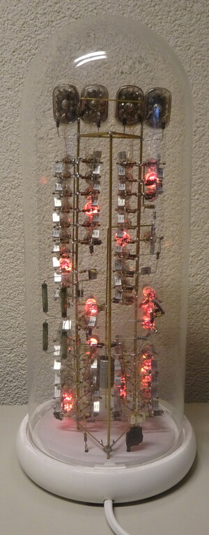
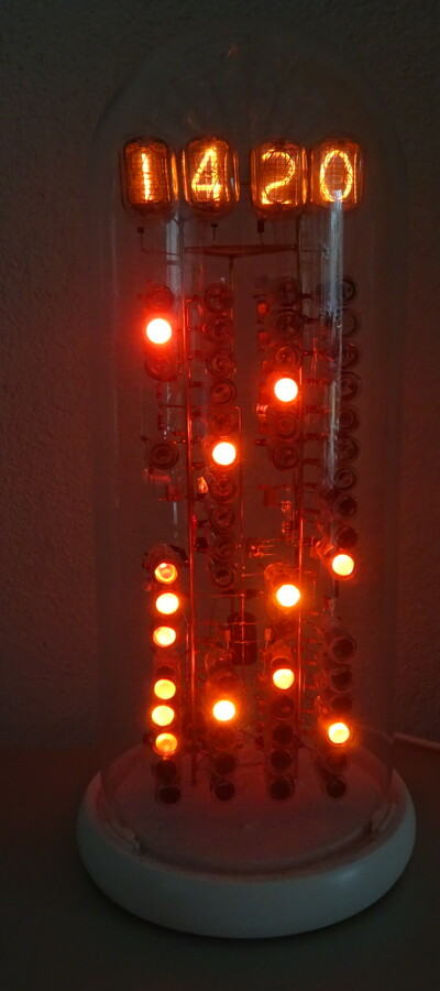 The picture shows my home-built digital clock, using Nixie tubes for readout.
In contrast to most other nixie clocks being built these days,
this clock does not use any transistor or IC for controlling and driving the tubes.
Instead, the driving logic is built from trigger tubes,
together with resistors, capacitors and silicon diodes.
A video is on youtube.
The picture shows my home-built digital clock, using Nixie tubes for readout.
In contrast to most other nixie clocks being built these days,
this clock does not use any transistor or IC for controlling and driving the tubes.
Instead, the driving logic is built from trigger tubes,
together with resistors, capacitors and silicon diodes.
A video is on youtube.
This project is a followup to a similar clock I built between 2002 and 2007, documented on its own page. That clock used regular NE-2 style neon lamps as logic elements. Unfortunately, after a while, as these lamps aged, the clock became unreliable and unusable.
The new clock uses trigger tubes, of the МТХ-90 type (that's in Cyrillic characters; transliterated to Latin script it's MTH-90), which are widely available as "new old stock" on Ebay. Trigger tubes are essentially regular neon lamps with an extra "trigger" electrode, which can be used to ignite them. However, in this circuit I don't use the trigger electrode. With the trigger electrode unconnected, these tubes have a striking voltage usually between 230 and 270 V, while their maintaining voltage is around 60 V. This large difference makes the circuit much less critical than with the NE-2 lamps, and I hope this will give the clock a long working life.
Update May 2, 2021: so far, so good! A week or so after completing the clock (in December 2020), one ring counter became unreliable in darkness. Adding two blue LEDs helped temporarily (ambient light helps to start the ignition process of the lamps), but I needed to replace one tube to make it reliable again. Since then, it has been working fine. The schematic has been updated to show the blue LEDs, the photographs not (yet).
Update October 31, 2021: Over the past months, a few more minor problems
have occurred and been fixed, but fortunately there still seems to be no problem with
tubes "drifting" out of spec, like in my earlier clock.
- The series resistor in the power supply increased its resistance, causing the
clock's supply voltage to become too low for reliable operation. Eventually, the
resistor even flamed briefly (see here),
and needed to be replaced.
- One 1N4007 diode became slightly leaky, and needed to be replaced.
This is surprising, as these diodes are rated for 1 A
and 1000 V, while here they see only a few mA and a few hundred volts.
- The "buffer" stage for the 25 Hz signal became unreliable. It turned
out this tube's ignition voltage had risen from about 150 V to about 200 V.
This tube's trigger electrode was connected to its cathode, to lower its ignition
voltage.
When these tubes operate, the cathode gets bombarded with positively charged ions, and is (or
should be) made to withstand this.
Due to connecting the trigger and the cathode, presumably the trigger electrode acted
as the cathode instead, and suffered this bombardment, causing it to wear out prematurely.
Inserting a 1 megaohm resistor between trigger and cathode
solves this: it still lowers the ignition voltage, but after ignition almost all
current flows through the cathode, as it should.
Update November 25, 2025: After almost 5 years, the clock is still performing well! The 25 Hz buffer stage lamp (see above) however did become unreliable again this year, again due to an increased ignition voltage. A better fix turned out to be to connect the 1 megaohm resistor between trigger and anode rather than cathode.
How the clock works
The main building block is a "ring counter": a set of trigger tubes (or simple neon lamps) connected such that any time, only one of them is lit, and whenever a pulse comes in, this glow moves on to the next lamp. Such a circuit is possible because a neon lamp requires a higher voltage to ignite ("striking voltage") than to remain on ("maintaining voltage"). Thus, if a voltage between those two is applied to the lamp (via a resistor) it will remain in the on or off state it is in, providing a form of memory.By cascading such counters, we can start with the 50 Hz mains frequency, and divide this by 2, by 5, by 5 again (then we're a 1 pulse per second), by 2, by 5, and finally by 6, to get 1 pulse per minute. Finally, four counters, with 10, 6, 10 and 3 positions respectively, count minutes, ten minutes, hours, and ten hours; each of these counters is connected to a Nixie tube for numerical display.
An extra bit of circuitry ensures that whenever an "illegal" hour
count appears, i.e., between 24 and 29, extra pulses are fed into the hour
counter to move on to the 00 position.
For setting the clock, a few reed-relays are provided which can be actuated
by holding a magnet near them (but safely outside the glass enclosure): this
connects the 1-pulse-per-second signal to one of the later counters to advance
it quickly.
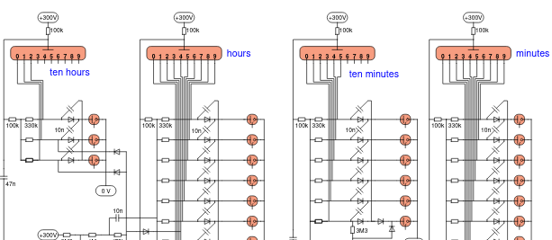
The entire schematic can be found here,
with some explanatory text.
The neon ring counters themselves are a well-known design, dating back to the 1950s or 1960s;
much more explanation and analysis of how they work can be found
on Ronald Dekker's website.
The way to cascade the counters, and to drive Nixies with them, are of my own design.
Keep in mind this schematic is as I built it, not how I would build it
if I would make another such clock.
For example, while building it I gradually got more insight in how best to
cascade the counters, so it is not done in the same way everywhere.
In line with that, I emphasize that the diagram is not meant as a recipe for building your own clock.
It may work, it may also not work.
Having said that, it's probably more reproducible than my previous clock.
But don't try unless you have enough understanding of the circuit and test equipment to debug problems yourself,
and know how to work safely with high voltages!
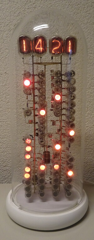
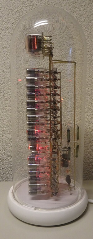
Mechanical construction
The basic structure consists of three vertical 1.8 mm thick brass rods, two of which carry two rows of lamps each, and the third one is in the back for mechanical support. With the benefit of hindsight, 1.8 mm is a bit thin for this, the structure is now more flexible than desirable. The rest of the wiring uses some 1.0 mm brass rods and lots of 0.1 mm enamelled copper wire.The enclosure is a ready-made glass cover with wooden base plate: it's this one, bought here. It comes with five white butterfly models inside, which weren't easy to remove. Because of the high voltages in the clock, the glass cover needed to be attached firmly to the base plate: for this, I had three clamps 3D-printed that fit on the glass cover's edge, and accept an M3 screw through the base plate.
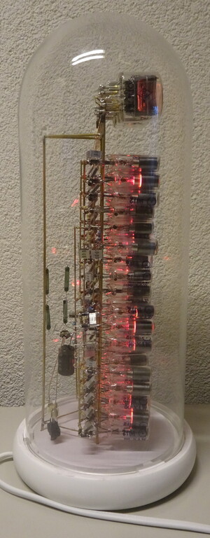
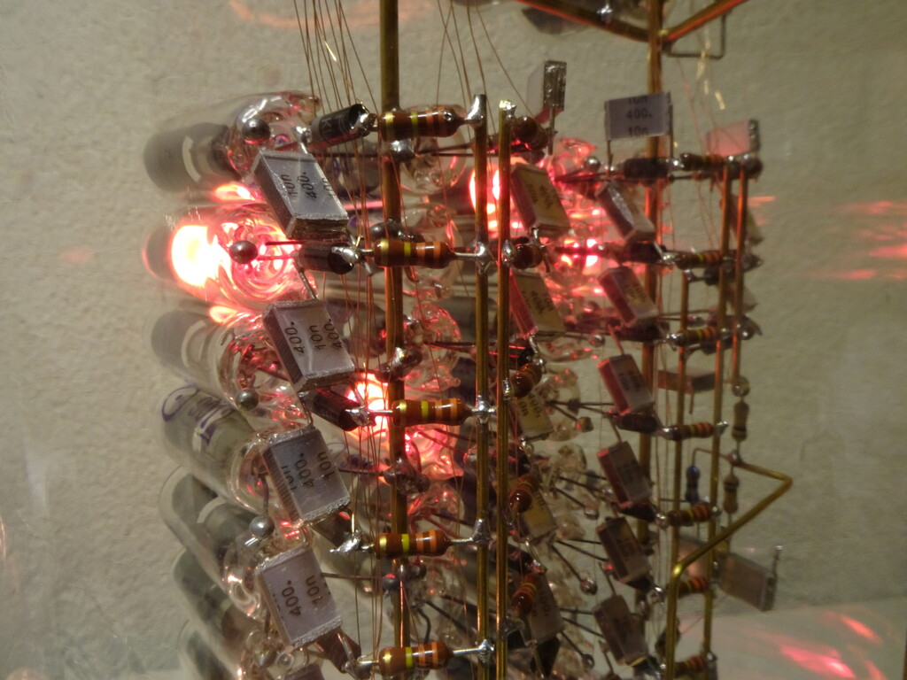
Some more pictures:
The physics
 When working with neon lamps, the difference between striking and maintaining
voltage is given as a fact of life.
However, it turns out that the physics behind it is quite interesting and easy to understand.
I learned most of this from a nice little book called "Electrische Gasontladingen"
by dr. F.M. Penning (1894-1953), who did a lot of
research on gas discharge
at Philips' physics laboratories.
(The pictures in this section are copied from his book.)
When working with neon lamps, the difference between striking and maintaining
voltage is given as a fact of life.
However, it turns out that the physics behind it is quite interesting and easy to understand.
I learned most of this from a nice little book called "Electrische Gasontladingen"
by dr. F.M. Penning (1894-1953), who did a lot of
research on gas discharge
at Philips' physics laboratories.
(The pictures in this section are copied from his book.)
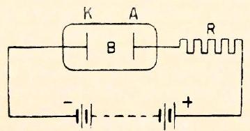
Consider a glass tube, filled with neon gas and containing two metal electrodes,
between which a voltage is applied.
Suppose one electron gets liberated from the cathode, e.g. due to ambient light.
This (negatively charged) electrode will be attracted by the (positively charged) anode, and thus
get accelerated.
On its way to the anode, it may bump into a neon atom.
If this happens at sufficient speed, an electron may be knocked off from the neon atom.
Then we have not 1 but 2 free electrons, and one positively charged neon ion.
The 2 free electrons are again accelerated towards the anode, may again bump into neon atoms, and so on:
an avalanche, resulting in some number of electrons reaching the anode.
O.t.o.h., the neon ions are attracted by the cathode, and when they bump into the
cathode, they may liberate an electron there.
If the above process is sufficiently "effective", namely so that for each free electron
that we start with, on average again at least 1 new electron is kicked out of the cathode,
the process can sustain itself: we then have an electric current flowing through the gas.
 How much voltage is needed for this?
Well, the electron needs to pick up sufficient speed before it hits a neon atom,
otherwise it can't knock off an electron.
How long it takes before the electron hits a neon atom depends on the pressure of the gas.
If the pressure is higher, there are more neon atoms around, so a higher voltage
is needed to accelerate the electron quickly enough before it bumps into a neon atom.
Conversely, at lower pressure, a lower voltage is enough.
But there's another problem if the pressure is too low: then there are so few neon
atoms around, that only a few collisions happen before the electron reaches the
anode. As a consequence, too few neon ions may be produced to liberate enough
new electrons from the cathode, as necessary for sustaining the discharge.
How much voltage is needed for this?
Well, the electron needs to pick up sufficient speed before it hits a neon atom,
otherwise it can't knock off an electron.
How long it takes before the electron hits a neon atom depends on the pressure of the gas.
If the pressure is higher, there are more neon atoms around, so a higher voltage
is needed to accelerate the electron quickly enough before it bumps into a neon atom.
Conversely, at lower pressure, a lower voltage is enough.
But there's another problem if the pressure is too low: then there are so few neon
atoms around, that only a few collisions happen before the electron reaches the
anode. As a consequence, too few neon ions may be produced to liberate enough
new electrons from the cathode, as necessary for sustaining the discharge.
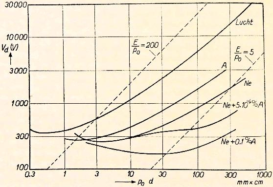
The result is the so-called Paschen curve, shown at the right.
This graph shows (on the
vertical axis) the voltage required to start a gas discharge, as a function of (on
the horizontal axis) the gas pressure times the distance between the
electrodes. That product basically tells how many neon atoms there are
between the cathode and the anode.
The curves have a clear but broad minimum,
representing a pressure and electrode distance combination that gives the lowest
striking voltage.
Note how adding 0.1 % of argon to the neon makes the striking voltage much lower:
this is called a Penning mixture.
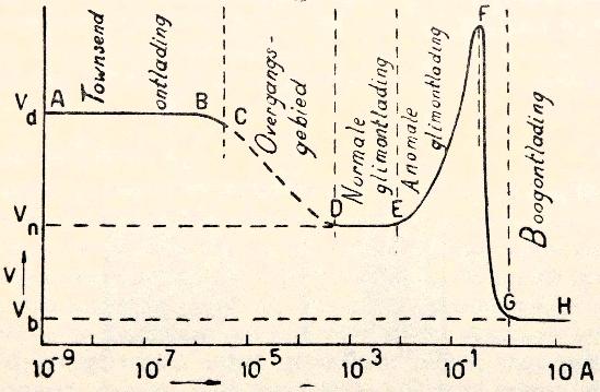 The above is only half the story: it describes the so-called Townsend discharge,
typically at currents of less than 1µA.
If sufficient current is allowed to flow, the Townsend discharge changes into
the so-called glow discharge ("glimontlading" in Dutch),
which is what we see in Nixie tubes and neon lamps
at current levels of a few mA.
The above is only half the story: it describes the so-called Townsend discharge,
typically at currents of less than 1µA.
If sufficient current is allowed to flow, the Townsend discharge changes into
the so-called glow discharge ("glimontlading" in Dutch),
which is what we see in Nixie tubes and neon lamps
at current levels of a few mA.
What happens there, is the following.
As noted before, positively charged neon ions will be floating around in the tube,
especially near the anode.
They are attracted to the cathode, but move there only slowly because they are so heavy.
So, there's a lot of free positive charge near the anode.
Effectively, this brings the positively charged anode closer to the cathode.
As a consequence, the electrons liberated from the cathode are accelerated faster,
so less voltage is needed for them to accelerate enough.
Or, in the Paschen graph, the smaller cathode/anode distance means we move to the left,
where the required voltage is lower. In fact, the positive space charge will grow until we're
at the minimum of the Paschen curve.
This is why the maintaining voltage of such a gas discharge is lower than the striking voltage!
"Clones"
The above page has inspired at least two readers to succesfully build similar clocks: Mike Mitchell here and on youtube, and Changliang Li here.On Ebay several (Chinese) sellers offer kits for nixie clocks in a round dome (search for 'nixie clock round glass'). Although they are driven by modern electronics, not trigger tubes, one wonders whether the choice of the enclosure was inspired by my clock.