Ultra-low power continuity tester
Pieter-Tjerk de Boer, PA3FWM web@pa3fwm.nlA continuity tester, also known as a contact tester, is basically a device with two test probes that beeps when the probes are in contact. This is very handy for e.g. tracing connections on a printed circuit board. A simple such tester is nothing more than a battery and a buzzer. However, the one described here is a bit more advanced.
 The continuity tester described on this page has the following properties:
- Only beeps if resistance between the test pens is less than 1 ohm (convenient so it will ignore most components on the board being tested).
- Never applies more than a few mV (so it won't damage any components, and won't make diodes or other PN juctions conduct).
- Never applies more than half a mA (again so it won't damage any components).
- Reacts quickly, in about 10 ms (essential when scanning a circuit board for contact).
- Needs no battery, being powered from a supercap which gets charged in a few seconds by plugging it into a USB outlet.
- Uses very little power (about 1 µA at about 3 V) when not beeping, so doesn't need an on/off switch.
- Uses little power (about 1 mA) when beeping.
- Is so small that the entire electronics can fit in one of the test probes.
The below schematic shows that the tester consists of three main parts:
an opamp-based circuit (around the TSU111, an ultra-low power opamp)
that "converts" the resistance between the probes
into a voltage;
a comparator (TS881) which compares this voltage to a threshold;
and a logic gate (74HC1G14) connected as an oscillator to drive the buzzer.
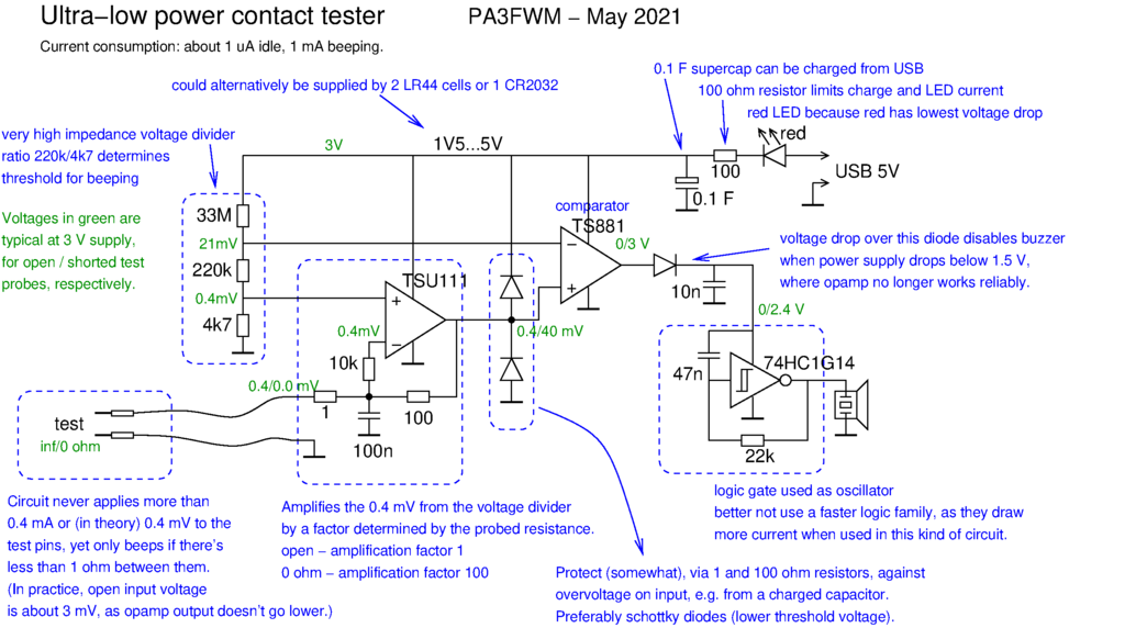
The main "trick" is the circuit around the TSU111 opamp,
which ensures that never much voltage or current is applied to the probes.
When the probes are open, the opamp acts as a voltage-follower, applying (ideally) 0.4 mV
to the probes.
When the probes are short-circuited, it acts as an amplifier with a gain of 100, resulting
in 40 mV at the output.
In this case, the 1 ohm input resistor limits the current through the probes to
0.4 mA (namely 0.4 mV over 1 ohm); it also limits the gain, which is important
as this opamp becomes too slow at higher gains.
When there's 1 ohm of resistance between the probes, the gain is 50,
so the opamp output voltage is 20 mV, etc.
The TSU111, TS881 and 74HC1G14 are unusual chips in hobbyist circuits,
but they are not expensive at major electronics distributors like Farnell.
And perhaps smaller more hobbyist-oriented electronics retailers
(with lower minimum order and shipping charges) can also be convinced to supply them.
Reasons that make the TSU111 so suitable for this circuit are
its very low power consumption, and its very low input offset voltage (less than 0.15 mV).
Because of the latter, no offset compensation circuitry and adjustment is needed.
Similarly, the TS881 was chosen for its very low power consumption.
The 74HC1G14 is not so unique; it could easily be replaced by a more common
chip containing not 1 but 4 or 6 gates, such as the 4093 or the 74HC14.
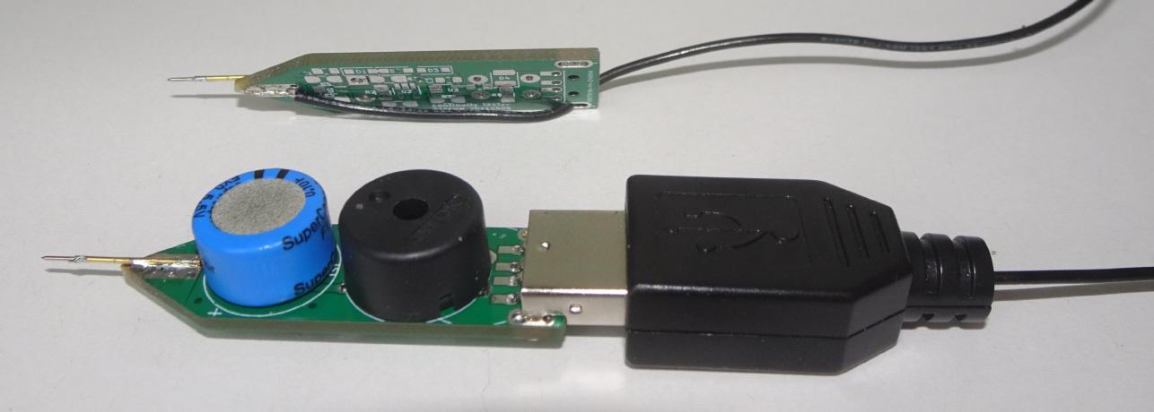
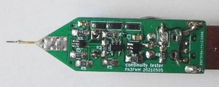 The picture shows how I built the circuit, on a small pcb of 50 by 14 mm.
The second probe sits on an identical, but otherwise empty, board (since the
well-known Chinese PCB factories make multiple copies of one's board anyway).
The probes are actually "pogo pins", assuming these have
a surface finish that will keep making reliable contact.
The pogo functionality itself is not useful here though, and introduces a few ohm
of resistance, so I soldered the inner and outer part of the pogo pin together.
The picture shows how I built the circuit, on a small pcb of 50 by 14 mm.
The second probe sits on an identical, but otherwise empty, board (since the
well-known Chinese PCB factories make multiple copies of one's board anyway).
The probes are actually "pogo pins", assuming these have
a surface finish that will keep making reliable contact.
The pogo functionality itself is not useful here though, and introduces a few ohm
of resistance, so I soldered the inner and outer part of the pogo pin together.
If you want to build your own, here are the KiCad files for the circuit board, and a sketch showing component placement and test points. Note that the KiCad files are a bit newer than the photographs on this page; some components have moved around, so don't take the photographs for guidance! The KiCad board has footprints that can accomodate resistors from 0603 to 1206 size, and the board can be directly plugged into a USB socket. If you prefer to solder a real USB connector on the board, you can chop off the part of the board; note that this intentionally cuts a trace (you don't want to short a data line to the power line), and then the LED needs to be mounted at a different place. I'm making these files available here only for non-commercial use, and without any guarantees!
Some possible ideas for variations on the circuit:
- Change the 220 kilo-ohm resistor to change the threshold for buzzing.
- Change the 47 nF capacitor and/or the 22 k resistor at the logic gate to change the tone pitch.
- Instead of a real USB connector, include a pattern on the circuit board so it can be plugged into a USB socket directly: cheaper, though perhaps less reliable. (This is already implemented in the supplied KiCad files.)
- Remove the LED: it's useful as an indicator of the charging of the supercap, but the voltage drop across it limits how far the supercap can be charged and thus how long one charge lasts.
- Power the circuit from a 3 V battery, instead of USB. Given the very low stand-by power consumption, such a battery should last many years even without an on/off switch. CR2032 batteries from discarded computers could probably provide long service, but unfortunately are large.
- Replace the TSU111 by a somewhat more power-hungry type which allows higher gain (see below why), and omit the TS881 (or use a single 4093 or 74HC132 for the comparator and oscillator functions) to simplify the circuit; however, then an on/off switch will be needed because of the higher idle power consumption.
Some ideas that will NOT work well: (and why)
- Increase the gain of the first opamp (TSU111) stage, e.g. by increasing the feedback resistor. Doing this would have the advantage of producing a larger output signal at this stage, allowing one to perhaps omit the comparator stage. However, this won't work well, due to this (ultra-low power) opamp's gain bandwidth product of only about 10 kHz. Suppose we would make the gain 10000 (so a 0.4 mV input swing would produce a full 4 V output swing), then the bandwidth is only 1 Hz, meaning the circuit takes about 1 second to respond. That's far too slow for practical use.
- Power the whole circuit from a single 1.5 V button cell. Unfortunately, the voltage of these cells gradually drops to about 0.9 V during use, while the TSU111 really needs at least 1.5 V to work properly (I tried).
- Omit the logic gate and let the comparator do double duty as an oscillator; I managed to get this to work, but it didn't "sound nice" due to how the frequency became dependent on the resistance between the probes.
This design was inspired by two sources.
 One is the contact tester published in Elektuur, a Dutch hobby electronics magazine,
internationally known as Elektor, back in 1982,
which I've been happily using for many years.
One is the contact tester published in Elektuur, a Dutch hobby electronics magazine,
internationally known as Elektor, back in 1982,
which I've been happily using for many years.
The Elektuur schematic is shown here.
Its essence is a voltage divider (R1/R2/R3) that produces about 2 mV across a 10 ohm resistor, by running some 0.2 mA through it.
Contact between the probes lowers this voltage further, which is detected by the opamp.
The disadvantage of this circuit is the power consumption: while the opamp could be
replaced by a modern very-low power type, unavoidably, about 0.2 mA is needed in the voltage divider.
One can't reduce this further because then the
voltage drop over a 1 ohm resistance between the probes would become too small to
reliably detect with an opamp.
Thus, this type of circuit needs an on-off switch and a real battery.
The original Elektuur article is on archive.org: April 1982 issue, page 44; or the English edition Elektor on page 42. A variation with an LED rather than a buzzer appeared in the July/August issue on page 62.
The other source of inspiration was this with the schematic having survived here. I found this design not work too well: it sends relatively much current through the probes and doesn't have a clear threshold for buzzing. However, it did inspire me to try to design something that is both ultra-low power and has the Elektuur design's good properties.