Phase and frequency modulation
Pieter-Tjerk de Boer, PA3FWM web@pa3fwm.nl(This is an adapted version of part of an article I wrote for the Dutch amateur radio magazine Electron, June 2019.)
 Phase modulation and frequency modulation are actually two different ways of looking
at the same signal, see the figure.
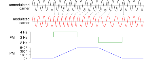
At the top, we see an unmodulated carrier, and below it a modulated carrier.
It is clearly visible that the frequency of the modulated carrier changes:
apparently there is frequency modulation (FM).
The frequency jumps back and forth between its rest value (unmodulated) and a higher
and a lower value, as indicated by the third line.
When the modulated carrier has a higher frequency, its phase is steadily more and more
ahead of the unmodulated carrier (up to 540 degrees in this example), and the other
way around; see the grey arrows.
This leads to the fourth line: the interpretation of the signal as phase modulation (PM).
Comparing the FM and the PM line, we see that the FM line is the mathematical derivative
of the PM line: the frequency (FM) indicates how fast the phase (PM) changes.
Conversely, the phase is the integral of the frequency.
Phase modulation and frequency modulation are actually two different ways of looking
at the same signal, see the figure.
At the top, we see an unmodulated carrier, and below it a modulated carrier.
It is clearly visible that the frequency of the modulated carrier changes:
apparently there is frequency modulation (FM).
The frequency jumps back and forth between its rest value (unmodulated) and a higher
and a lower value, as indicated by the third line.
When the modulated carrier has a higher frequency, its phase is steadily more and more
ahead of the unmodulated carrier (up to 540 degrees in this example), and the other
way around; see the grey arrows.
This leads to the fourth line: the interpretation of the signal as phase modulation (PM).
Comparing the FM and the PM line, we see that the FM line is the mathematical derivative
of the PM line: the frequency (FM) indicates how fast the phase (PM) changes.
Conversely, the phase is the integral of the frequency.
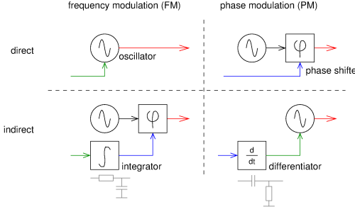 This theoretical knowledge is useful for actually building FM or PM transmitters,
see the second figure.
A trivial FM transmitter consists of a voltage controlled oscillator, top left in the figure:
the modulation signal directly controls the frequency.
Similarly, a trivial PM transmitter consists of a fixed oscillator followed by a voltage-controlled
phase shifter, top right in the figure.
But we can also make FM by taking the trivial PM transmitter and first integrating
the modulation signal, see bottom left.
And similarly, we can make PM by feeding the modulation via a differentiator to the FM transmitter,
see bottom right.
This theoretical knowledge is useful for actually building FM or PM transmitters,
see the second figure.
A trivial FM transmitter consists of a voltage controlled oscillator, top left in the figure:
the modulation signal directly controls the frequency.
Similarly, a trivial PM transmitter consists of a fixed oscillator followed by a voltage-controlled
phase shifter, top right in the figure.
But we can also make FM by taking the trivial PM transmitter and first integrating
the modulation signal, see bottom left.
And similarly, we can make PM by feeding the modulation via a differentiator to the FM transmitter,
see bottom right.
Differentiation and integration may sound dramatic, but can be done using simple RC circuits. An RC low-pass filter acts as an integrator, for frequencies above its cut-off frequency: applying a constant voltage to its input will make its output voltage rise steadily. Similarly, an RC high-pass filter acts as a differentiator for frequencies below its cut-off frequency.
In practice, for analog FM transmissions (both wideband FM for broadcast, and narrowband FM for communication by e.g. amateurs) preemphasis and deemphasis are used. This means that at the transmit side a high-pass filter is used to amplify the higher modulation frequencies, and a low-pass filter is used at the receiver to undo this. This is done to reduce noise: noise at higher frequencies will be attenuated extra at the receiving side. The cut-off frequency of this filter is 3.2 kHz for broadcast FM in Europe (RC time constant 50 µs). Since a high-pass filter acts as a differentiator, it changes FM into PM (bottom right in the previous figure). So what is called FM in practice, is actually a combination of FM up to 3 kHz, and PM above that!