Ethernet hardware
Pieter-Tjerk de Boer, PA3FWM web@pa3fwm.nl(This is an adapted version of part of an article I wrote for the Dutch amateur radio magazine Electron, January 2023.)
Over the past decades, computer networks have become omnipresent, and as a consequence many older generations of 'ethernet' hardware have ended on the scrap heap or amateur radio fleamarkets. Although this material is called 'ethernet', it does not use of what we call the 'ether' in radio context. Let's have a look at how these networks worked and why they are called 'ethernet', and which parts are usable for our analog radio signals.
A coaxial ether
 The first widely used forms of ethernet ran at 10 megabits per second and used a coaxial cable.
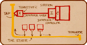
The figure shows the original sketch used by Bob Metcalfe to explain his ethernet ideas in 1976 [1] (allegedly - since I found multiple, different versions online).
The yellow line labeled 'the ether' is simply a coaxial cable.
The idea is that each station continuously 'listens' on the cable, and only transmits if it hears that no other station is transmitting.
This way, the cable looks like the 'ether' from radio technology, hence the name.
When a station transmits, its signals propagate to both ends of the cable and thus reach all other connected stations.
At both ends there are 50 ohm resistors to 'terminate' the cable, so signals are not reflected.
The first widely used forms of ethernet ran at 10 megabits per second and used a coaxial cable.
The figure shows the original sketch used by Bob Metcalfe to explain his ethernet ideas in 1976 [1] (allegedly - since I found multiple, different versions online).
The yellow line labeled 'the ether' is simply a coaxial cable.
The idea is that each station continuously 'listens' on the cable, and only transmits if it hears that no other station is transmitting.
This way, the cable looks like the 'ether' from radio technology, hence the name.
When a station transmits, its signals propagate to both ends of the cable and thus reach all other connected stations.
At both ends there are 50 ohm resistors to 'terminate' the cable, so signals are not reflected.
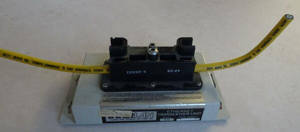 The first ethernet installations used a 10 mm think, rather stiff yellow cable,
which was allowed to be up to 500 m long.
Because of the thick cable, it was also called 'thicknet'.
Because this cable was too stiff to let it run by every computer, a separate device called 'transceiver'
was clamped onto the cable and connected to the computer via a short, flexible cable.
The transceiver featured a pin that punched a hole through the outer layers of the cable
to contact the center conductor: the so-called 'vampire tap'.
The first ethernet installations used a 10 mm think, rather stiff yellow cable,
which was allowed to be up to 500 m long.
Because of the thick cable, it was also called 'thicknet'.
Because this cable was too stiff to let it run by every computer, a separate device called 'transceiver'
was clamped onto the cable and connected to the computer via a short, flexible cable.
The transceiver featured a pin that punched a hole through the outer layers of the cable
to contact the center conductor: the so-called 'vampire tap'.
Later, a thinner coaxial cable came into use. Its attenuation per meter was larger, so it was only allowed to be 185 m long, but it was flexible enough to reach every computer, so external transceivers were no longer needed. Such a network was also called 'thinnet' or 'cheapernet'.
Coaxial 10 Mbit/s systems have been out of fashion for a quarter century by now. In older office buildings there is probably still a lot of that thick coaxial cable: disused, but hard to get out. And because of the vampire taps it's not waterproof anymore, making reuse as an antenna cable harder.
Galvanic isolation
 The electric signals used on both kinds of coaxial cable were the same.
When a station starts to transmit, it makes the center conductor negative by pulling it (in the rhythm
of the data) to −9 V, with a current limit of 80 mA.
Those 80 mA ran through both parallel 50 ohm terminations, making the voltage on the center conductor −2 V.
If multiple stations transmit simultaneously, their combined current would pull the center conductor
more negative: this was used to detect 'collisions'. After a colllision, both stations would stop
transmitting and retry after a random delay.
The electric signals used on both kinds of coaxial cable were the same.
When a station starts to transmit, it makes the center conductor negative by pulling it (in the rhythm
of the data) to −9 V, with a current limit of 80 mA.
Those 80 mA ran through both parallel 50 ohm terminations, making the voltage on the center conductor −2 V.
If multiple stations transmit simultaneously, their combined current would pull the center conductor
more negative: this was used to detect 'collisions'. After a colllision, both stations would stop
transmitting and retry after a random delay.
The entire cable had to be galvanically isolated from the rest of the computer. As a consequence, ethernet boards for PCs had a rather characteristic structure: the part in the upper yellow dotted line in the figure. First of all, it has a BNC connector that is isolated from the chassis. The actual transceiver (80 mA current source, collision detection, etc.) is one chip, usually a DP8392 or similar. This chip 'floats' w.r.t. the rest of the computer. To enable that, power was supplied to it from a DC/DC converter: 5 V in, isolated 9 V out. To galvanically isolate the data signals between the DP8392 and the big chip at bottom right, three signal transformers were used, which are together in a black plastic box.
The BNC connector, the DC/DC converter and the signal transformers can also be used for other purposes. And the terminations are nice QRP dummyloads for HF: according to the specifications, they can handle at least 0.5 watt and should not deviate by more than 1 % from 50 ohms between 0 and 20 MHz, so their SWR is better than 1:1.01.
Ethernet over UTP cable
Modern ethernet setups use UTP cable: Unshielded Twisted Pair, or shielded variants of that. Such cable contain 8 wires, in four pairs, each consisting of two wires twisted together. Each such a pair is a fine transmission line with an impedance of 100 ohms. Such a cable is no longer passed by all computers as in the first figure, but in star topology: from each computer to a centrally located switch. So, not much is left of the original 'ether' idea, other than the name.One possible amateur use of UTP cable is to split take it apart to get four separate twisted pairs, and use those as antenna cable. It is cheap, lighter than coax, symmetric (so no balun needed at a dipole feed point), and so thin that it can be fed through a door or window opening without drilling holes. It does have more attenuation than coaxial cable, see the sequel.
Another possibility is what, among others, LZ1AQ does in his active antennas [2]: use one pair for radio signals and the other pairs for power supply and control.
Signal transformers
Also when UTP cable is used, the computer should be galvanically isolated from the cable. But that is much easier than in the coaxial case, where an entire IC needed to be isolated. For UTP, they simply connect each wire pair via a transformer to the 'big' chip that does all the rest of the processing. The ethernet card shown earlier has both a coaxial connection and the UTP connection. The isolated part for UTP is within the lower yellow dotted line in the figure. The transformers are in a black plastic block, together with some other components, together often called the 'magnetics'.
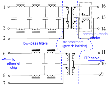 The next figure (based on the 20F001 datasheet) shows a typical internal circuit of such a transformer block for 10 Mbit/s ethernet.
At left we see low-pass filters, of 7th order for transmit (top) and 5th order for receive (bottom).
Those are quite steep filters: while the cut-off frequency is 17 MHz, at 30 MHz the attenuation is
already 32 and 20 dB, respectively (according to the datasheet).
In the center we see the actual transformers for the galvanic isolation.
At right we see a common-mode choke, in this case only in the transmit branch;
this forces the current in both wires of a pair to be equal.
Thus, both wires produce an equal but opposite magnetic field in their environment,
preventing the cable from 'radiating'.
The next figure (based on the 20F001 datasheet) shows a typical internal circuit of such a transformer block for 10 Mbit/s ethernet.
At left we see low-pass filters, of 7th order for transmit (top) and 5th order for receive (bottom).
Those are quite steep filters: while the cut-off frequency is 17 MHz, at 30 MHz the attenuation is
already 32 and 20 dB, respectively (according to the datasheet).
In the center we see the actual transformers for the galvanic isolation.
At right we see a common-mode choke, in this case only in the transmit branch;
this forces the current in both wires of a pair to be equal.
Thus, both wires produce an equal but opposite magnetic field in their environment,
preventing the cable from 'radiating'.
On ethernet boards that also support 100 Mbit/s or more, transformer blocks are used that do not have low-pass filters, because those higher speeds require higher signal frequencies. On boards that also support gigabit speeds, the blocks contain not two but four transformers, because for gigabit all four pairs are used. And switches and routers often contain blocks with even more transformers, namely for multiple UTP ports. Finally, there are also ethernet boards where the 'magnetics' are not a separate component, but are integrated inside the RJ45 connector.
Homebrew mixer
 Of course, these transformers can also be used for radio signals in the HF range.
Datasheets with the pinout can often be found on the internet, and if not, the pinout
can be found experimentally.
Of course, these transformers can also be used for radio signals in the HF range.
Datasheets with the pinout can often be found on the internet, and if not, the pinout
can be found experimentally.
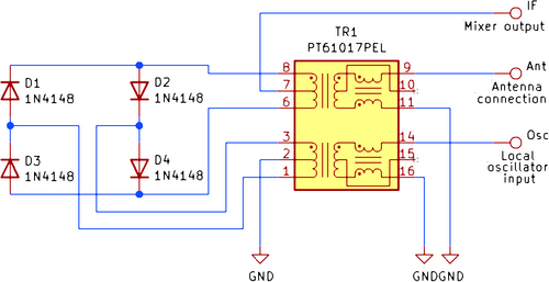
The figure (copied from [3]) shows a homebuilt ring mixer using ethernet transformers. The oscillator signal alternately makes D1 and D2 conduct, or D3 and D4. Thus, alternately pin 6 or pin 8 of the transformer is connected to ground, so the antenna signal is alternately passed on to the IF output with or without inversion.
Actually, the story behind the schematic from [3] is noteworthy: what if you want to listen to shortwave to listen to independent news sources, but due to war circumstances can't buy suitable equipment? You may have an old mediumwave radio lying around, and using components from discarded computers a converter from HF to mediumwave can be built: four diodes, the ethernet transformers, and a crystal oscillator.
References
[1] https://grouper.ieee.org/groups/802/3/ethernet_diag.html[2] https://www.lz1aq.signacor.com/docs/wsml/wideband-active-sm-loop-antenna.htm
[3] https://hackaday.com/2022/03/17/owning-a-shortwave-radio-is-once-again-a-subversive-activity/
Text and pictures (except the first and last) on this page are copyright 2023, P.T. de Boer, web@pa3fwm.nl .
Republication is only allowed with my explicit permission.