The Zwischenbasis circuit
Pieter-Tjerk de Boer, PA3FWM web@pa3fwm.nl(This is an adapted version of part of an article I wrote for the Dutch amateur radio magazine Electron, October 2023.)
In March 2023, Wellbrook Communications announced the end of their antenna production because the owner (Andrew Ikin) was retiring (sadly, he passed away about half a year later [13]). On the groups.io loopantennas forum this led to quite some discussion, because Wellbrook active loopantennas are generally seen as the best of the best. What would be a good successor? And why are these antennas so good? One of the things mentioned in that discussion is that Wellbrook used the little-known 'zwischenbasis' circuit. Let's have a look at how this works, and see that wheels are sometimes reinvented and even patented.
The 'Zwischenbasisschaltung'
What could a Zwischenbasisschaltung be? Translated literally from German, it means 'in-between base circuit', suggesting something special is done with the base connection of a transistor. However, this is not the case. The circuit and its name date back to the vacuum tube era. What is called the 'common (or grounded) cathode circuit' in English, was called 'Katodenbasisschaltung' in German (and similarly of course for grid and anode). In other words, where the word 'common' or 'grounded' is used in English, German used the word 'Basis', which translates to 'base' in English. With the advent of the transistor this of course became confusing, so since then they generally omit the 'basis' part of the word. But in the name 'Zwischenbasisschaltung' the vacuum tube terminology lives on.
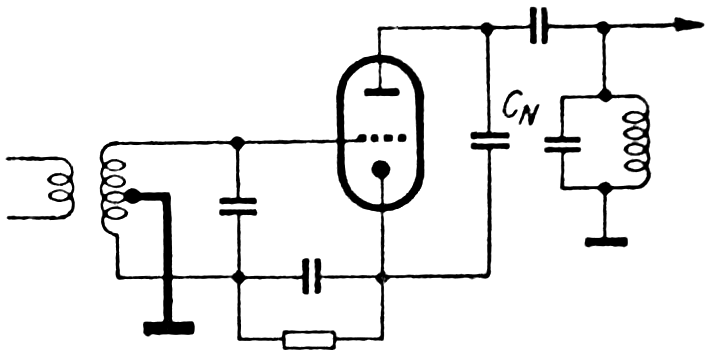 The figure shows the Zwischenbasisschaltung as proposed by Rudolf Cantz in 1953 [1].
In his time this was of course implemented with a vacuum tube, but the same principle
can be applied to a transistor.
We see that the input signal is connected, via a transformer, between the grid and the cathode of the tube.
The anode is the output.
In contrast to the usual circuits, none of the three tube (or transistor) connections is connected
to ground for AC.
The ground is connected to a tap on the secundary of the input transformer,
so in between the grid and the cathode. Hence the name 'Zwischenbasisschaltung',
as 'zwischen' means 'between'.
The figure shows the Zwischenbasisschaltung as proposed by Rudolf Cantz in 1953 [1].
In his time this was of course implemented with a vacuum tube, but the same principle
can be applied to a transistor.
We see that the input signal is connected, via a transformer, between the grid and the cathode of the tube.
The anode is the output.
In contrast to the usual circuits, none of the three tube (or transistor) connections is connected
to ground for AC.
The ground is connected to a tap on the secundary of the input transformer,
so in between the grid and the cathode. Hence the name 'Zwischenbasisschaltung',
as 'zwischen' means 'between'.
B.t.w., in his article [1] Cantz simply calls it 'neue Gegenkopplungsschaltung', i.e., 'new feedback sircuit'. He introduces the name 'Zwischenbasisschaltung' in his patent [2]. Translating the name into Englisch isn't easy, so in English literature it has become common to use the untranslated 'zwischenbasis' name.
The application Cantz had in mind was the input stage of FM broadcast receivers, and he mentions several advantages. The circuit gives him the freedom to choose the input impedance by choosing which turn of the secondary coil he connects to ground. The range goes from one extreme, namely grounding the cathode, to the other, grounding the grid. For his application these resulted in too high and too low input impedances, respectively, so this extra freedom was useful. Another advantage is that the 'neutrodynisation' is less cricitical. A tube in a grounded-cathode circuit at these frequencies tends to oscillate due to feedback via the tube's internal capacitance between anode and grid. This can be compensated using a 'neutrodynisation capacitor', CN in the circuit diagram, which introduces an equal but opposite feedback via the input transformer. The grounded-grid circuit doesn't suffer from this problem because the grid is grounded. The zwischenbasis is in between: neutrodynisation is still needed, but less critical. Finally Cantz observes that with the Zwischenbasisschaltung the matching for minimal noise and maximal gain are nearly equal.
B.t.w., in all circuits shown here the DC bias circuitry is omitted, as is usual in the literature. Of course it is needed for the circuits to work in practice, but not for discussing the principles.
'Katodeneingangsverstärker mit teilweiser Unterkopplung'
 Although Cantz is usually credited with the invention of the Zwischenbasis,
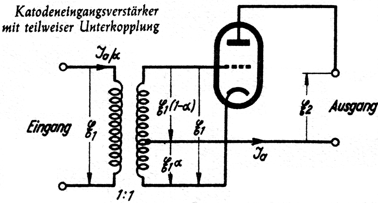
the circuit shows up in earlier literature, namely in Funkschau in 1948 [3], see the figure.
That article is about various tube circuits in which the cathode is not grounded.
They call this particular circuit 'Katodeneingangsverstärker mit teilweiser Unterkopplung'.
The first word indicates that the cathode is the input, like in the grounded-grid circuit.
But because of the input transformer's grounded tap, the input signal only partially goes to
the cathode, hence the second part of the name: 'partial undercoupling'.
Although Cantz is usually credited with the invention of the Zwischenbasis,
the circuit shows up in earlier literature, namely in Funkschau in 1948 [3], see the figure.
That article is about various tube circuits in which the cathode is not grounded.
They call this particular circuit 'Katodeneingangsverstärker mit teilweiser Unterkopplung'.
The first word indicates that the cathode is the input, like in the grounded-grid circuit.
But because of the input transformer's grounded tap, the input signal only partially goes to
the cathode, hence the second part of the name: 'partial undercoupling'.
'Base-emitter feedback'
 Ulrich Rohde (DJ2LR) has drawn attention to the circuit several times in the English-language
literature, but without using the 'zwischenbasis' name or referring to Cantz.
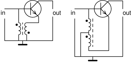
In his book [4] he calls the circuit 'base-emitter feedback', and thus emphasizes the fact
that there's a form of feedback from the emitter to the base.
This is clearly visible in the left half of the figure (copied from [4]).
At first glance this looks different from Cantz's circuit, but it isn't.
The primary and the secundary coil of the transformer are both grounded on one side,
and the dots which indicate the winding direction show that this grounding point is actually
a center tap, just like in Cantz's circuit; this is clarified in the re-drawn version at the right.
Rohde writes that this is the only circuit he knows in which simultaneously the noise figure is minimal,
the amplification is maximal and the input reflection loss is minimal.
Ulrich Rohde (DJ2LR) has drawn attention to the circuit several times in the English-language
literature, but without using the 'zwischenbasis' name or referring to Cantz.
In his book [4] he calls the circuit 'base-emitter feedback', and thus emphasizes the fact
that there's a form of feedback from the emitter to the base.
This is clearly visible in the left half of the figure (copied from [4]).
At first glance this looks different from Cantz's circuit, but it isn't.
The primary and the secundary coil of the transformer are both grounded on one side,
and the dots which indicate the winding direction show that this grounding point is actually
a center tap, just like in Cantz's circuit; this is clarified in the re-drawn version at the right.
Rohde writes that this is the only circuit he knows in which simultaneously the noise figure is minimal,
the amplification is maximal and the input reflection loss is minimal.
'Passive augmentation'
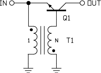 The next figure (from [5]) shows a circuit with 'passive augmentation', invented and patented by Chris Trask, N7ZWY.
Like in the previous figure, the transformer boils down to a single coil with a grounded center tap,
However, the base and emitter have changed position: the input signal is now applied between
emitter and ground, like in a normal common-base circuit.
The next figure (from [5]) shows a circuit with 'passive augmentation', invented and patented by Chris Trask, N7ZWY.
Like in the previous figure, the transformer boils down to a single coil with a grounded center tap,
However, the base and emitter have changed position: the input signal is now applied between
emitter and ground, like in a normal common-base circuit.
Thanks to that transformer this circuit has an even lower input impedance than the usual common-base circuit. If, when the input current varies, the input voltage would e.g. tend to go up, the transformer pulls the base voltage down, which works against the input voltage change. So the input voltage varies (even) less than in the usual common-base circuit, so the input impedance is (even) lower. Trask shows that with a 1:2 turns ratio and a hFE of 100, the input impedance decreases by 85%. Furthermore he mentions that the passive augmentation improves the noise figure and the intermodulation performance.
Note that Cantz uses his circuit to achieve an input impedance in between that of the common-base and common-emitter circuits, while Trask uses the 'same' circuit to make the input impedance very low. That seems contradictory. The difference is due to how the input signal is fed into the circuit: Cantz does this via a transformer between grid and cathode (or base and emitter, respectively), while Trask connects it between emitter and ground. (The obvious third option would be to connect it between base and ground, which is what Rohde did, see above.) In the end, from the transistor's point of view there is no difference; the transformer that is needed anyway to ground a point 'between' base and emitter, can do double duty to transform the input impedance.
Active loop antennas
A conductive loop, small compared to the wavelength and made of e.g. copper tubing, can be used as an antenna in two ways.The first way is by connecting it to a (variable) capacitor, bringing the loop into resonance. The resonance lead to a high(er) efficiency (relatively less loss), which is needed if it is to be used for transmission, and also gives stronger signals for reception. But the disadvantage is that it is a narrow-band system: it needs to be tuned to the desired frequency.
The alternative is not to resonate the loop, but directly connect it to the input of an amplifier. That makes it a wideband receive-only antenna, which can e.g. receive the entire long, medium and shortwave range. However, one must make some effort to make this sensitive enough: the antenna and amplifier's own noise must be weaker than the noise received from the outside. Furthermore, the large-signal behaviour of the amplifier must be very good to avoid intermodulation.
Wideband loop antennas for reception often employ an amplifier with a very low input impedance. Such an amplifier effectively short-circuits the loop, and 'measures' the resulting current. The advantage of this is that the sensitivity is constant over a large frequency range. For a given field strength the induced voltage in the loop is proportional to the frequency, but so is the reactance of the loop's self-inductance, so the short-circuit current remains the same.
Wellbrook antennas
The schematics of the Wellbrook loop antenna's amplifier are kept secret, for obvious commercial reasons, and the circuit board is potted, to protect it both from the weather and from prying eyes. However, something is known about it. M1GEO disassembled a broken and older version of the amplifier to repair it and has drawn the schematic [6]. A Chinese reverse-engineered schematic of a newer version has briefly circulated on the Internet. And Wellbrook's own website [7] also reveals something:The design comprises of 8 very high gain JFETs in parallel push-pull with a Bipolar transistor cascode stage to extended bandwidth. A very low amplifier noise floor is achieved by dynamically decreasing the JFET Source resistance to a fraction of an Ohm. This is achieved using a proven technique developed by Dr. Ulrich L. Rohde in the 1970s by coupling the FET Gate to the Source with a phase inverting transformer.This indeed very much sounds like a FET-based version of passive augmentation or the zwischenbasis circuit: the FET's source input impedance is lowered by coupling the gate and the source via a transformer.
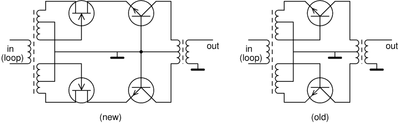 Based on all this information, the adjacent sketch results,
with the new version at the left and the old version of the design at the right.
Each JFET stands for four of them in parallel,
connected in zwischenbasis via the input transformer.
The NPN transistors in the new schematic are in 'normal' common-base circuit,
and form a cascode with the JFETs.
The entire thing is symmetric (push-pull) to suppress even-order intermodulation products.
The old version does not have JFETs; there the NPN transistors themselves are connected in zwischenbasis.
Based on all this information, the adjacent sketch results,
with the new version at the left and the old version of the design at the right.
Each JFET stands for four of them in parallel,
connected in zwischenbasis via the input transformer.
The NPN transistors in the new schematic are in 'normal' common-base circuit,
and form a cascode with the JFETs.
The entire thing is symmetric (push-pull) to suppress even-order intermodulation products.
The old version does not have JFETs; there the NPN transistors themselves are connected in zwischenbasis.
Of course, it's quite a job, even an art, to get from such a concept sketch to a well-working circuit: the DC bias, turns ratios in the transformers, and transistor types all have to be chosen suitably. Furthermore, the website tells us that the amplifier also has rising input impedance versus frequency to match the loop's reactance. All of that is the 'secret sauce' of the Wellbrook design.
Other active loop antennas
In fact, more designs have been published for loop antenna amplifiers using 'passive augmentation' or the zwischenbasis.First of all of course Trask's own design [5]. That circuit is a lot more complex: like the Wellbrook it has two stages and is push-pull, but rather than a combination of JFET and NPN, it uses only four NPN transistors, each with its own feedback transformer for the passive augmentation. Furthermore there's a coupling transformer at the input, one at the output, and also one between both stages; and there's an input balun. Eight times coil winding fun...
Other schematics can be found at [8] and [9]. All have a push-pull input stage with passive augmentation. But they differ in such aspects as whether the second stage is also push-pull, also has passive augmentation, and to what extent coupling and feedback transformers are separate or combined. The Wellbrook circuit with just two transformers is one extreme, and Trask's with seven the other extreme.
On the other hand, in discussions in the loopantennas group, the LZ1AQ design [10] is often judged to be the second-best; that design has the transistors in 'normal' common-base circuit, without passive augmentation.
Who was first?
 As is clear from the above, the Zwischenbasisschaltung has been published many times in the literature
under various names; here I've selected only some which introduce a new name or a different
perspective.
It isn't quite clear whether the various authors and engineers independently arrived at the same
circuit, perhaps starting from different ideas, or in fact knew about each other's work.
As is clear from the above, the Zwischenbasisschaltung has been published many times in the literature
under various names; here I've selected only some which introduce a new name or a different
perspective.
It isn't quite clear whether the various authors and engineers independently arrived at the same
circuit, perhaps starting from different ideas, or in fact knew about each other's work.
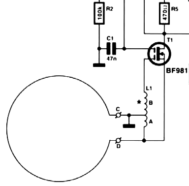
The idea of using this circuit in an active loop antenna does seem to have been invented several times independently. Trask published and patented his ideas between 2001 and 2010, while the Wellbrook design existed already in 1996 [11], but with a potted and therefore secret circuit. Someone else was ahead of both of them though, even if his design did not get well known: in the Dutch magazine Elektuur of February 1995 [12] we find the figure shown here, designed by J. Barendrecht. We clearly recognize the zwischenbasis circuit, this time implemented with a dual-gate MOSFET and without push-pull.
References
[1] R. Cantz: Hochfrequenzverstärkung mit Trioden, Telefunken Röhre H.30, 1953. https://www.radiomuseum.org/forumdata/users/133/PDF/Crantz_ZwischenBasis.pdf[2] Rudolf Cantz: Hochfrequenzvorstufe für ultrakurze Wellen, patent DE973118, 1953
[3] Wolfgang Kautter: Katodengekoppelte Verstärker, Funkschau, nr. 1, 1948.
[4] Ulrich L. Rohde, T.T.N. Bucher: Communications Receivers - Principles & Design, chapter 5.6. 1988
[5] Chris Trask, N7ZWY: A High Dynamic Range Amplifier for Wideband Active Loop Antennas, 2010.
[6] https://www.george-smart.co.uk/projects/wellgood-loop/wellgood-loop-history/
[7] https://web.archive.org/web/20211205233950/https://www.wellbrook.uk.com/loopantennas/FLX1530LN-flexible-loop
[8] https://web.archive.org/web/20240422054237/http://www.ik4hdq.net/doc/testi/loop_lb.pdf (at the time of publication this was still at ik4hdq.net, but that site seems to have disappeared, hence this archive.org link)
[9] https://groups.io/g/loopantennas/files/Loop%20Amp%20using%20Trask%20Augmentation%20by%20Alain%20%22SWL%20FE7523%22
[10] https://www.lz1aq.signacor.com/docs/wsml/wideband-active-sm-loop-antenna.htm
[11] https://groups.io/g/loopantennas/message/11648
[12] Aktieve antenne voor 100 kHz...50 MHz (ontwerp J. Barendrecht), Elektuur, 2/1995
[13] https://groups.io/g/loopantennas/message/18386 (and a personal note from his daughter at https://swling.com/blog/2024/01/andrew-ikin-of-wellbrook-communications-has-passed-away/#comment-942219 )
Text on this page is copyright 2023, P.T. de Boer, web@pa3fwm.nl .
Republication is only allowed with my explicit permission.