Gilbert cell mixers
Pieter-Tjerk de Boer, PA3FWM web@pa3fwm.nl(This is an adapted version of part of an article I wrote for the Dutch amateur radio magazine Electron, May 2023.)
The NE602 mixer, famously used in many amateur circuits, will be going out of production this year, together with its brothers NE612, SA602, SA612. So it's time to find an alternative, and read up on how such chips work.
Mixing: adding or multiplying?
Depending on the context, 'mixing' two analog signals (like voltages) may mean either adding or multiplying them. In case of e.g. audio signals, mixing means adding; think of a mixing console in an audio recording studio, or the 'mixer' settings in your computer. When voltages are added, no new frequencies arise. In radio technology however, a mixer is a circuit in which sum and difference frequencies arise. To achieve that, the voltages must be multiplied. A very common circuit for doing that is, albeit unjustly, known as the 'Gilbert cell'.Principle of the Gilbert cell
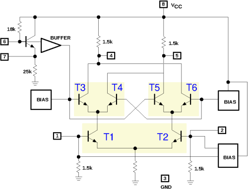 The figure (copied from the datasheet) shows the internal circuit of the NE602,
which is also a textbook example of the Gilbert cell.
The figure (copied from the datasheet) shows the internal circuit of the NE602,
which is also a textbook example of the Gilbert cell.
First consider transistors T1 and T2. Their emitters are connected so both of their emitter currents flow through the common emitter resistor to ground. In other words, this emitter current is partitioned by the two transistors among their collectors. If both bases (available as pins 1 and 2 of the chip) are at the same voltage, the current will be equally shared. If pin 1 is positive w.r.t. pin 2, T1 will conduct a bit more and T2 a bit less, so a larger part of their joint emitter current will be sent to T3 and T4 than to T5 and T6; and vice versa of course if pin 1 is negative w.r.t. pin 2.
This repeats at T3 and T4, and at T5 and T6. They too will distribute their joint emitter currents based on their base voltages. If T3's base is positive w.r.t. T4's base, more current will go the left collector resistor; and otherwise more to the right collector resistor. T5 and T6 do the same, but reversed, due to the crosswise connection of their collectors to those of T3 and T4.
Let's consider the voltage between the bases of T1 and T2 as one input (pins 1 and 2 of the chip),
and the voltage between the bases of T3 and T4 (and also T5 and T6) as the other input (pin 6).
Then we see that if both inputs are positive, most current will go the left collector resistor (via T1 and T3);
this will also happen if both inputs are negative (but via T2 and T6).
But if one input is negative and the other is positive, most current will go to the right collector resistor
(via T1 and T4, or T2 and T5).
The output of the circuit is the voltage between pins 4 and 5;
this is positive or negative depending on which collector current is largest.
Result: plus and plus gives plus; plus and minus gives minus; and so on:
that is a multiplication!
 And if (at least) one input is 0, then both collector resistors get equal currents,
regardless of the other input (thanks to how T5 and T6 are connected crosswise to T3 and T4);
that also fits a multiplication.
Unfortunately this multiplication is not nicely linear though, as we will see later.
And if (at least) one input is 0, then both collector resistors get equal currents,
regardless of the other input (thanks to how T5 and T6 are connected crosswise to T3 and T4);
that also fits a multiplication.
Unfortunately this multiplication is not nicely linear though, as we will see later.
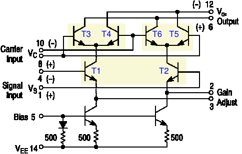
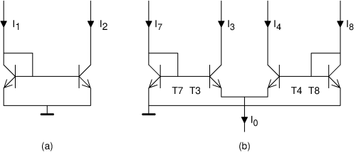
The next figure shows another mixer chip, the MC1496. Here we see again the same combination of six transistors. But this chip is more basic than the NE602: the user needs to connect some resistors for DC bias, and there's no pre-amp in front of T3...T6 (which in the NE602 can also be used as an oscillator). On the other hand, the MC1496 does not have a simple emitter resistor, but two current sources (the two transistors at the bottom), and the user can connect a resistor between the emitters of T1 and T2.
Long-tailed pair
In the Gilbert cell mixer we saw three copies of the same sub-circuit, consisting of two transistors with their emitters connected. This sub-circuit is known as a 'long-tailed pair', see figure (a) below. Let's calculate precisely what it does.
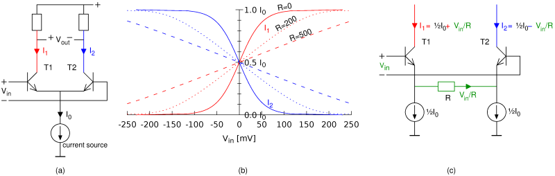 For transistors in general, it holds that the collector current is proportional
to exp(VBE/25 mV).
Practically this means that for every increase of the BE voltage by 17 mV,
the collector current doubles.
So if the input voltage (applied between both bases) is 17 mV,
the transistor at the left wants to draw 2 times as much collector current as the transistor at the right.
Their total remains I0, forced by the current source.
So the left transistor gets ⅔I0 while the right transistor gets ⅓I0.
Similarly, at an input voltage of 34 mV, the transistors get 80% and 20% of I0.
This is sketched as the solid lines in figure (b):
clearly, the relation between the input voltage and both output currents is not linear.
This also means that the Gilbert cell, which is based on how the long-tailed pairs
distribute the current, does not work linearly.
For transistors in general, it holds that the collector current is proportional
to exp(VBE/25 mV).
Practically this means that for every increase of the BE voltage by 17 mV,
the collector current doubles.
So if the input voltage (applied between both bases) is 17 mV,
the transistor at the left wants to draw 2 times as much collector current as the transistor at the right.
Their total remains I0, forced by the current source.
So the left transistor gets ⅔I0 while the right transistor gets ⅓I0.
Similarly, at an input voltage of 34 mV, the transistors get 80% and 20% of I0.
This is sketched as the solid lines in figure (b):
clearly, the relation between the input voltage and both output currents is not linear.
This also means that the Gilbert cell, which is based on how the long-tailed pairs
distribute the current, does not work linearly.
Figure (c) shows a variant of the long-tailed pair with a resistor R between the emitters. As long as Vin is 0, this makes no difference: there's 0 volts across the resistor, so no current flows through it, and both collector currents are ½I0 again. If Vin is not zero, and we (for simplicity) assume that both BE voltages are constant (the well-known 0.6 volts), then the full Vin is across the resistor. Because the current sources will insist on drawing ½I0 each, the current Vin/R must go via the transistors: one of them will thus have ½I0 + Vin/R and the other ½I0 - Vin/R. The difference is precisely Vin/R.
As noted before, this is under the assumption that the BE voltages are equal. In reality, they will change a little with the collector currents and as a consequence the relation will be a little bit non-linear. See the dotted lines in figure (b): the larger R, the better the linearity, but also the smaller the gain.
So, now we understand the function of the resistor that can be connected between pins 2 and 3 of the MC1496: it allows the user a choice between more linearity or more gain. On the other hand, the NE602 is hard-wired for maximum gain, and indeed, this chip is renowned for not having good intermodulation performance (linearity). For both chips it holds that the second input, driving T3...T6, is non-linear; for their linearity the emitter resistor does not help.
Gilbert's multiplier
 Although the mixer circuit discussed above is known as the 'Gilbert cell',
it was invented by Howard E. Jones [3].
Barrie Gilbert is the inventor of a different, though similar, circuit.
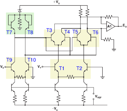
One of the first chips featuring this circuit was the AD534, of which the
internal schematic is shown here.
The circuit around T1...T6 looks very similar to the earlier circuits,
but the essential difference is the addition of T7 and T8.
They ensure that the mixer is also linear for its second input (via T9 and T10).
Although the mixer circuit discussed above is known as the 'Gilbert cell',
it was invented by Howard E. Jones [3].
Barrie Gilbert is the inventor of a different, though similar, circuit.
One of the first chips featuring this circuit was the AD534, of which the
internal schematic is shown here.
The circuit around T1...T6 looks very similar to the earlier circuits,
but the essential difference is the addition of T7 and T8.
They ensure that the mixer is also linear for its second input (via T9 and T10).
 To understand how Gilbert achieved this, we first have to study another sub-circuit
from analog chip technology, the so-called 'current mirror', see figure (a).
This circuit contains two transistors; current I1 is the input
and current I2 is the output.
The voltage on the base of the left transistor will settle such that its collector current
will be I1 (we ignore the base current for the moment).
Because of the exponential relation between base-emitter voltage and collector current,
this base voltage will thus be proportional to the logarithm of the input current.
This same BE voltage is also the BE voltage of the transistor at the right,
and its collector current depends exponentially on it.
The final result is that I2 depends linearly on I1,
despite the transistors themselves being non-linear!
To understand how Gilbert achieved this, we first have to study another sub-circuit
from analog chip technology, the so-called 'current mirror', see figure (a).
This circuit contains two transistors; current I1 is the input
and current I2 is the output.
The voltage on the base of the left transistor will settle such that its collector current
will be I1 (we ignore the base current for the moment).
Because of the exponential relation between base-emitter voltage and collector current,
this base voltage will thus be proportional to the logarithm of the input current.
This same BE voltage is also the BE voltage of the transistor at the right,
and its collector current depends exponentially on it.
The final result is that I2 depends linearly on I1,
despite the transistors themselves being non-linear!
Inspired by the current mirror which was already well-known by then (1968), Gilbert arrived at the circuit shown in (b). This resembles two current mirrors, T7+T3 and T5+T8, except that not all emitters are connected together. The base-emitter-junctions together form a loop, and looking carefully, one sees that the BE voltage of T7 minus that of T3, must equal the BE voltage of T8 minus that of T4. Because of the exponential relation between the BE voltage and collector current for each transistor, it follow that I7 / I3 = I8 / I4. Written differently, I7 : I8 = I3 : I4. Furthermore, we still have I3 + I4 = I0 (again ignoring the base current). Now, if I0 is from a current source (and thus constant), and we treat I7 and I8 as input signals, then this circuit will divide I0 over I3 and I4 in the same proportion as I7 to I8. Written as a formula: I3 = I0 · I7 / (I7+I8). That's a very neat multiplication if I7+I8 is kept constant. But it only works for positive numbers (as the transistors don't allow negative currents).
To also work with negative numbers, we need a bit more, and that's how we arrive at the schematic of the AD534 shown earlier. There T3...T8 form Gilbert's actual multiplier. T1 and T2 form a long-tailed pair with emitter resistor for good linearity, and so do T9 and T10. They convert the input voltages Vx and Vy into differential currents; differential means that the difference between two currents is the actual signal. So, the input voltage Vx determines the difference between the collector currents of T1 and T2. Next, just like in the first figure, T1's collector current is divided among T3 and T4, and T2's among T5 and T6; but thanks to the presence of T7 and T8 this division is now precisely in the ratio of the collector currents of T9 and T10, and thus of the input voltage Vy. (Note that T7 and T8 are 'upside down' compared to figure (b), but they still have the same functionality.) Thus, we obtain a nicely linear multiplication, for both positive and negative input voltages Vx and Vy.
For completeness: the four non-numbered transistors at the bottom of the AD534 circuitry are again current sources, and around opamp A1 an amplifier is constructed to convert the differential output current of T3...T6 into a non-differential output voltage.
Jones vs. Gilbert
We now have the circuit from the first figure (the NE602) which was invented by Jones but is known as the 'Gilbert cell', and the circuit from the fourth figure (the AD534) that Gilbert invented but which does not really go by any name. The circuits look similar, so the confusion is understandable. It seems Gilbert invented his circuit without knowing Jones's, and he has tried to correct the naming; but once a wrong name is in common use, it's hard to change that.In mixer applications (like the MC1496 and NE602), one almost always sees Jones's circuit. The only advantage Gilbert's circuit offers, is that it is also linear for the second input signal. For a mixer that is usually not needed. The second input signal is usually used for the local oscillator, and if that gets distorted a bit, harmonics arise which usually are not much of a problem. In fact, mixing is often intentionally done with a square-wave signal; for example in diode ring mixers, the diodes work as switches that are switched on and off by the oscillator signal. This can also be done in the Gilbert cell (we'll continue using that name for Jones's design): if one applies a large AC voltage between the bases of T3/T5 and T4/T6, these transistors act as switches that send T1's and T2's collector currents entirely to one or to the other collector resistor.
More about Barrie Gilbert
 As far as I know, not much was heard from Jones in electrical engineering, other than his mixer circuit.
In contrast, Gilbert (1937-2020) has had a rich career, upon which he looks back in [5].
In his youth he was already building televisions.
Working at Mullard he got fascinated by oscilloscope technology, which lead him to a job at Tektronix, where he also invented his multiplier circuit.
Later he worked for a long time as a chip designer at Analog Devices.
As far as I know, not much was heard from Jones in electrical engineering, other than his mixer circuit.
In contrast, Gilbert (1937-2020) has had a rich career, upon which he looks back in [5].
In his youth he was already building televisions.
Working at Mullard he got fascinated by oscilloscope technology, which lead him to a job at Tektronix, where he also invented his multiplier circuit.
Later he worked for a long time as a chip designer at Analog Devices.
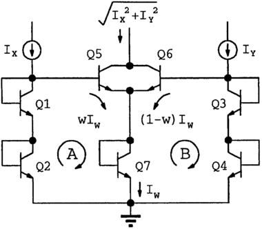
In figure (b) we saw that he used the exponential relationship between current and voltage in a transistor to multiply currents nicely linearly. (By the way, this is similar to how a slide rule performs multiplication by adding distances.) Later he generalized this idea and called it the 'translinear principle'. It can be used to design various circuits that perform mathematical operations on currents and voltages. For example, the circuit shown here 'calculates' Pythagoras's formula, √(x2+y2).
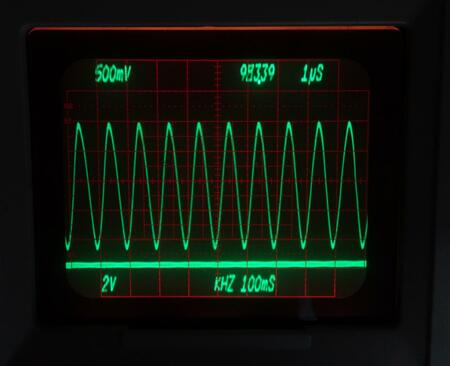 His most visible contribution, at least in a literal sense, is the system used by Tektronix 7000-series oscilloscopes
for showing the settings (volts and microseconds per division) as digits and letters on the the screen.
In modern oscilloscopes the screen is a computer monitor, capable of showing any text.
But the 7000 series was still analog, with a cathode-ray tube in which the electron beam is deflected horizontally and vertically to draw the waveform.
Gilbert designed a set of (analog!) chips that generate signals that steer the electron beam to draw digits and letters on the screen [9].
At that time (around 1970) this was an enormous luxury!
His most visible contribution, at least in a literal sense, is the system used by Tektronix 7000-series oscilloscopes
for showing the settings (volts and microseconds per division) as digits and letters on the the screen.
In modern oscilloscopes the screen is a computer monitor, capable of showing any text.
But the 7000 series was still analog, with a cathode-ray tube in which the electron beam is deflected horizontally and vertically to draw the waveform.
Gilbert designed a set of (analog!) chips that generate signals that steer the electron beam to draw digits and letters on the screen [9].
At that time (around 1970) this was an enormous luxury!
Obsolete or not?
Jones's and Gilbert's designs both date back to the 1960s, and mixer chips like the MC1496, NE/SA602/612, SO42P were designed in the 1970s. Apparently, there is not much demand anymore for such mixer chips. That makes sense, because nowadays one doesn't put a single mixer but an entire receiver into a chip, and/or the signal processing is largely done digitally. Production of the SO42P has long been discontinued. NXP (formerly Philips/Signetics) is the only manufacturer of the NE602 and its siblings, and has decided to stop the production this year. They'll be available here and there for a while, but at some point stocks will get exhausted.The four-quadrant multiplier AD534 was brought to market in 1977. In 2006 it was already on display in a showcase on 'Obsolete Analog Computing Technology' in the London Science Museum [11]. But that was premature, because the chip is still being manufactured as of 2023. Apparently, there still is a demand for this kind of chips, but they are much more expensive than the mixers mentioned before.
I haven't really found a good alternative for the NE602. One quickly arrives at the venerable MC1496, which is still being manufactured but less easy to use: it requires a higher supply voltage and external DC biasing, and has no built-in oscillator. Or one arrives at modern chips that are meant for frequencies in the GHz range, are often in amateur-unfriendly tiny smd packages, and again have no built-in oscillator.
References
 [1] NE/SA602A datasheet, Philips, 1990.
[2] MC1496 datasheet, ON Semiconductor, 2006.
[3] Howard E. Jones: Dual output synchronous detector utilizing transistorized differential amplifiers; U.S. patent 3241078A (registered 1963).
[4] Barrie Gilbert: A Precise Four-Quadrant Multiplier with Subnanosecond Response, IEEE Journal of Solid-State Circuits, Dec. 1968. Reprinted in [7].
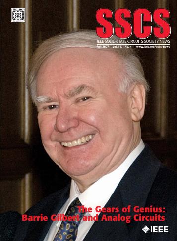
[5] Barrie Gilbert: The Gears of Genius, in [7].
[6] Thomas H. Lee: Tales of the Continuum: A Subsampled History of Analog Circuits, in [7].
[7] IEEE SSCS News, Fall 2007.
https://sscs.ieee.org/images/files/newsletter_archive/sscs_newsletter_200710.pdf
[8] Barrie Gilbert: Translinear circuits, an historical overview. Analog Integrated Circuits and Signal Processing, 1996.
[9] Barrie Gilbert: Monolithic Analog READ-ONLY Memory for Character Generation, IEEE Journal of Solid-State Circuits, Feb. 1971.
[10] https://www.nxp.com/pcn/202208013DN
[11] James M. Bryant: Analog Computation in the Digital Age. 2006. https://www.analog.com/media/en/analog-dialogue/raqs/computation.pdf
Text and pictures (except the first and last) on this page are copyright 2023, P.T. de Boer, web@pa3fwm.nl .
Republication is only allowed with my explicit permission.