Thermal noise
Pieter-Tjerk de Boer, PA3FWM web@pa3fwm.nl(This is an adapted version of part of an article I wrote for the Dutch amateur radio magazine Electron, October 2022.)
This article is about noise. Not the man-made noise from solar panels and consumer electronics, but the so-called thermal noise. We take a closer look at what happens inside a copper wire; how electrons move back and forth, 'producing' noise in the proces. We end with a practical application in active antennas.
Gas
A gas, like air, consists of lots of individual particles, atoms or molecules, flying aound and occasonally bumping into each other. In such a collision, they exchange energy: one molecule moves a bit slower after the collision, the other a bit faster., and also their directions can change. It's like a collision between two billiard balls: the speeds and directions after the collision can be calculated in principle, and depend strongly on, among others, the angle at which the two balls (molecules) hit each other. So, if one would know both the speed and the position of all molecules in a gas at some specific moment, one could in principle calculate everything happening in that gas in the future.However, there are a lot of molecules. One liter of air at room temperature contains about 2.5 · 1022 molecules. Computing the behaviour of each of them is far too much work, even for a modern computer. (And that's apart from whether it is possible to know the speed and position of all those molecules; quantum mechanics tells us there are fundamental limits to this.)
That's why physicists, such as Maxwell and Boltzmann, already in the 19th century chose a totally different approach. Rather than computing the behaviour of every molecule separately, they chose a statistical approach. They only wanted to know how the speeds are distributed; i.e., which percentage of the molecules has which speed. They arrived at a very nice result, the so-called 'equi-partition principle'. This says that, on average, there's equally much energy, namely ½kT, in each so-called degree of freedom. A degree of freedom is e.g. the speed of a molecule in the x direction, the y direction, or the z direction; or the speed of rotation of a molecule around an axis, or the amplitude of a vibration inside the molecule. In the formule T is the absolute temperature, expressed in kelvins, and k is Boltzmann's constant, 1.38 · 10-23 joule per kelvin. At room temperature, about 290 K, this boils down to ½kT = 2 · 10-21 joule per degree of freedom; that is very little energy, but don't forget that we have very many molecules.
In our three-dimensional world there are three independent directions for the speed (x, y, z; or east/west, north/south, up/down), so three degrees of freedom, so in total an energy of ³⁄₂kT, which is 6 · 10-21 joule per molecule. If a molecule of mass m moves at speed v, it has a kinetic energy of ½mv². A typical air molecule (nitrogen or oxygen) weighs about 5 · 10-23 grams, and with that ³⁄₂kT worth of kinetic energy has an average speed of some 500 meter per second.
Copper wire
That gas is nice, but usually our electricity flows through solid matter, such as a copper wire. In solid matter, the atoms or molecules are in fixed positions; they can vibrate a bit, but not really move to a different place. A characteristic of metals is that although the atoms' nuclei stay in place, one (or more) electrons per atom can in fact move around freely, so these electrons are no longer bound to their 'own' atom. This free movement of electrons makes metals conduct electricity.Those free electrons are pretty similar to a gas, and therefore are often called an electron gas. Again, they get on average ½kT energy per degree of freedom. In total, at room temperature, this is again 6 · 10-21 joule per electron, just like in a gas per molecule. But an electron is (even) much lighter than a gas molecule, namely about 9 · 10-28 grams. As a consequence, with the same energy it moves (even) faster: on average some 100 km/s !
(Actually, the above is too simple. If one also takes quantum-mechanical effects into account,
the average speed of the free electrons is another 10 times higher.
But that doesn't matter for our discussion here.)
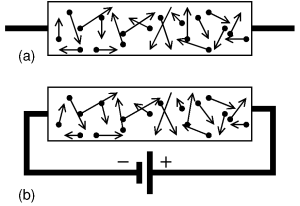
Note that said 100 km/s is in a random direction. In total, on average, there are equally many electrons moving to the left as to the right, so the net result is that this thermal movement transports no charge; there's no net current, see (a) in the figure.
This changes if we connect a voltage source, e.g. with the negative pole at the left and the positive right, as in figure (b). Suppose the wire has a thickness of 1 mm², is 60 m long and consists of copper, then its resistance is 1 ohm. If we apply 1 volt, a current of 1 ampère will flow. 1 ampère is 1 coulomb worth of charge per second. One electron carries a charge of 1.6 · 10-19 coulomb, so per second about 6 · 1018 electrons flow through our wire. Per mm³ of copper there are about 8.4 · 1019 free electrons, so it follows that, at said current of 1 ampère, the electrons move at a speed of about 0.07 mm/s.
This is very much less than the 100 km/s that we calculated earlier for the random motion of the electrons! So, even though we may have the mental image of the electrons moving nicely and orderly, reality is much more chaotic. Even without a voltage applied, the electrons are already moving around like crazy. And when a voltage is applied, those movements become just a little bit asymmetric, moving just a little bit more to the right than to the left, which results in a net current flowing. Compare figure (a), without a voltage source, to (b) with a voltage source: the electrons move around randomly, but while in (a) they, on average move equally much to the left and to the right, in b) they move on average a bit more to the right, attracted by the voltage source's positive pole.
Noise
Now suppose we take a resistor and don't connect anything to it. Such a resistor is effectively just a piece of wire, possibly rolled up. We now know that even if nothing is connected to the wire, the electrons in it still move back and forth at high speed. As a consequence, sometimes there will be more electrons at the left end of the resistor, and sometimes more at the right. So, there's a fluctuating voltage on the resistor, all by itself!How high is that voltage? We can say something about that by connecting the resistor to a capacitor (or considering the capacitance between the wire ends). Energy can be stored in a capacitor, so it is one of the degrees of freedom of the system, and we've learnt that each degree of freedom will get, on average, an energy ½kT. A capacitor with a capacitance C, charged to a voltage V, contains an energy ½CV². Setting ½kT equal to ½CV², and assuming e.g. C=10 pF, then we find that at room temperature the average voltage V on the capacitor is 20 µV. The larger C, the lower this voltage; e.g., at 100 nF it's only 0.2 µV. That makes sense: a larger capacitor flattens the fluctuations. With some more calculation it follows that for a resistor of R ohms, at absolute temperature T kelvin, in a bandwidth of B Hz, the average noise voltage is √4kTBR. So, a higher resistor produces more noise.
Perpetuum mobile
It's important to realize that the noise from the resistor is not a production fault, or merely a practical limitation. It is a fundamental property of a resistor; it is not possible to make a resistor that produces less noise than √4kTBR (no matter how much a manufacturer would want to).Suppose someone would manage to make a resistor which does not produce noise at room temperature. Then I would connect that resistor to a normal, noisy resistor of the same value. The noise voltage from my normal resistor would send a current through the noiseless resistor, and as a consequence the noiseless resistor would warm up. If I wait long enough, I could heat my house with it or drive a steam engine: a perpetuum mobile! (I would have to be very patient though, because of how small Boltzmann's constant is, but that doesn't detract from the principle.)
Such a perpetuum mobile cannot exist of course (because of the law of conservation of energy). The 'solution' for this is that every resistor at the same temperature produces precisely equally much noise (namely √4kTBR). That ensures that if you connect two resistors, each resistor delivers equally much noise-power to the other, so they both stay at the same temperature. (B.t.w., one could also 'solve' the problem by assuming the noisy resistor, when connected to the noiseless resistor, cools down. Then energy conservation is still satisfied, so we don't have a perpetuum mobile. However, then still the second law of thermodynamics would be 'tresspassed', which says that heat can only flow spontaneously from a warmer to a colder body, not the other way around.)
In physics the theory behind this necessary noise production of resistors is called the 'fluctuation-dissipation-theorem'. This theorem describes a direct link between how much energy a system can dissipate (convert to heat), and how much fluctuation (noise) that same system produces. Our resistor is just an example of this: there's a direct link between its resistance and the noise voltage. Another example is the fact that a black object can absorb light and get warm in the process; the reverse of this is that such an object emits noise. At room temperature, that noise is mostly invisible infrared light, but if you heat up the object sufficiently, it will be red hot: the red glow is noise.
 This also holds when you make the system more complicated.
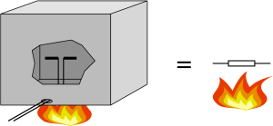
The figure depicts a half-wave dipole with a 73 ohm impedance in an all-absorbing box at a temperature of 400 kelvin.
The inside walls of the box emit noise in the form of radiowaves, appropriate for 400 K.
That noise is received by the dipole and converted into an electric voltage at its terminals.
That noise voltage is precisely as large as the voltage across a loose 73 ohm resistor heated to 400 K.
Again this must be the case; if not, one could make a perpetuum mobile.
This also holds when you make the system more complicated.
The figure depicts a half-wave dipole with a 73 ohm impedance in an all-absorbing box at a temperature of 400 kelvin.
The inside walls of the box emit noise in the form of radiowaves, appropriate for 400 K.
That noise is received by the dipole and converted into an electric voltage at its terminals.
That noise voltage is precisely as large as the voltage across a loose 73 ohm resistor heated to 400 K.
Again this must be the case; if not, one could make a perpetuum mobile.
Carbon resistors
Some resistors, for example older carbon resistors, produce more noise than other resistors, for example modern metal film resistors. Does this allow us to make a perpetuum mobile by connecting such a carbon resistor to metal film resistor? No; the extra noise is only there if one sends an (extra) current through the carbon resistor, and when one does that, one is supplying extra energy to the system so it's not a perpetuum mobile. Without the external current source the carbon resistor will not produce more (or less) noise than the metal film resistor.Bias circuit for an active antenna
 Finally, the long-awaited practical application.
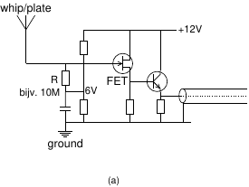
See figure (a), showing the schematic of an active antenna.
We see a FET whose gate is connected to a piece of metal (whip or plate).
The gate is also connected to a DC voltage, typically about half the supply voltage,
via a many-megaohm resistor,
This is the bias voltage which allows the FET to do its job without the output
being limited by the available supply voltage.
Finally, the long-awaited practical application.
See figure (a), showing the schematic of an active antenna.
We see a FET whose gate is connected to a piece of metal (whip or plate).
The gate is also connected to a DC voltage, typically about half the supply voltage,
via a many-megaohm resistor,
This is the bias voltage which allows the FET to do its job without the output
being limited by the available supply voltage.
 But what about the noise contribution of this high resistance?
Won't that overpower the weak signals from the antenna?
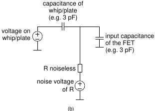
To explore this, consider figure (b), which is the equivalent schematic resulting from reducing the circuit to its essence.
The whip or plate is a voltage source (the signal being received) in series with a capacitance of a few pF.
The FET is a capacitive load of also a few pF.
And our noisy resistor is replaced by a noiseless resistor, in series with a voltage source representing
the resistor's noise voltage.
But what about the noise contribution of this high resistance?
Won't that overpower the weak signals from the antenna?
To explore this, consider figure (b), which is the equivalent schematic resulting from reducing the circuit to its essence.
The whip or plate is a voltage source (the signal being received) in series with a capacitance of a few pF.
The FET is a capacitive load of also a few pF.
And our noisy resistor is replaced by a noiseless resistor, in series with a voltage source representing
the resistor's noise voltage.
Seen from the point of view of the noise voltage source, the circuit is an RC low-pass filter. The antenna's capacitance and the FET's capacitance are in parallel, and thus get added. Assuming e.g. R = 10 MΩ and 3 + 3 = 6 pF worth of capacitance, the cut-off frequency of this low-pass filter is 2.7 kHz.
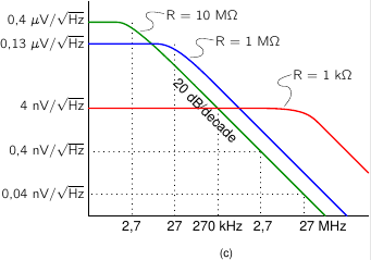 The resulting voltage at the gate, as a function of frequency, is shown in figure (c).
At frequencies below the cut-off, the noise voltage is independent of frequency,
again √4kTBR.
But above the cut-off, the noise decreases by 20 dB per decade, or a factor of 10 (in voltage) per factor of 10 in frequency.
The resulting voltage at the gate, as a function of frequency, is shown in figure (c).
At frequencies below the cut-off, the noise voltage is independent of frequency,
again √4kTBR.
But above the cut-off, the noise decreases by 20 dB per decade, or a factor of 10 (in voltage) per factor of 10 in frequency.
As we increase the resistance, its own noise increases, proportionally to √R. But at the same time, the cut-off frequency decreases, proportional to 1/R. And because 1/R goes 'faster' than √R, the end result at frequencies above the cut-off is that the noise decrease as the resistance increases. This is demonstrated by the various lines for various values of R.
So, we get 'lucky' here. We need to choose R large in order not to lose (short-circuit) the signals from the antenna, and we might fear that such a large R adds too much noise. But because at larger R the cut-off of the low-pass filter moves, there's in fact less noise left at larger R !
At very low frequencies the noise does increase with increasing R, but that's not really a problem. Firstly, there aren't many radio signals at such low frequencies; and secondly, natural noise sources, especially atmospheric ones, are so strong there that they still overpower the resistor's noise.
References
[1] Neil. W. Ashcroft, N. David Mermin: Solid State Physics, 1976.[2] Pierre Grivet, Austin Blaquière: Le bruit de fond, 1958.
[3] Peter Eastman: Introduction to Statistical Mechanics. https://web.stanford.edu/~peastman/statmech/
[4] Considerans Radio-Amateur van het Jaar 2018. http://www.vederfonds.veron.nl/considerans2018.html