3D-printed low-pass filters
Pieter-Tjerk de Boer, PA3FWM web@pa3fwm.nl(This is an adapted version of an article I wrote for the Dutch amateur radio magazine Electron, August 2026.)
At the output of a transmitter, a low-pass filter is needed to suppress harmonics. In the HF range, such a filter is usually built using coils wound on toroidal cores. Here I describe an alternative, using air-cored coils wound on 3D-printed coil formers, exploiting the mutual coupling between the coils to make the filter steeper.
The start
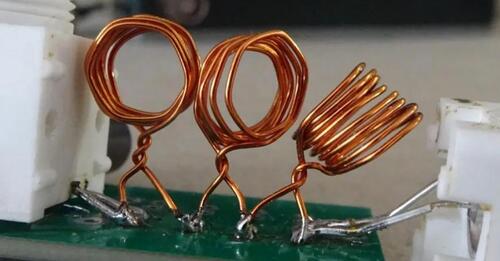 It all started when I was building a small transmitter for the 10m band,
and didn't feel like using toroidal cores.
There are three reasons for using toroids for coils in such filters:
(i) they give more inductance with fewer turns;
(ii) they are reproducible, just get the right number of turns on the right type of toroid;
(iii) there's little coupling between neighbouring coils, as the magnetic field is largely confined to the interior of the toroid.
On the 10 m band, one doesn't need that much inductance, so (i) didn't really apply. (ii) is true, but as an experiment one can deviate from this. Then (iii) remains: how much trouble is the mutual coupling between air-wound coils going to give? I just gave it a try: the picture shows a 7th-order low pass filter with three air-wound coils and four capacitors (smd, not visible). The network analyzer showed that it worked just fine! Depending on how the coils were bent, the mutual coupling could even be benificial, by giving notches in the stop band: frequencies at which the filter has (almost) infinite attenuation.
Notches
 Notches in low-pass filters are not unusual, but they are usually not created by having coupled coils.
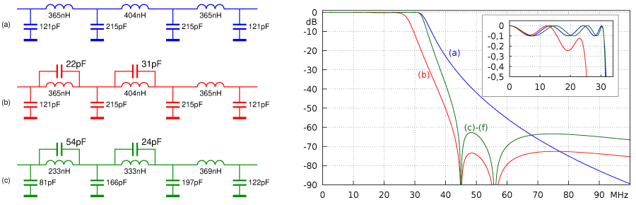
The figure shows three low-pass filters and their characteristics.
Design (a) is a rather normal 7th-order low-pass; the passband extends to 31 MHz, with 0.1 dB of ripple,
and an attenuation of 60 dB is achieved from 63 MHz onwards.
In design (b) capacitors have been put in parallel to two coils from (a), chosen for resonance at 45 and 56 MHz. At the resonance frequency, the impedance of a parallel LC circuit is (in principle) infinitely high, giving a notch at that frequency. An extra advantage is that the transition from passband to stopband becomes steeper: 60 dB attenuation is now achieved already at 42 MHz. But we also see that the passband has been distorted: the filter now already starts attenuating at about 25 MHz, and the passband ripple is no longer equal everywhere.
To rectify that, the component values need to be changed a bit, as done in (c). The passband is now nice again, while the notches are still at 45 and 56 MHz. -60 dB is now achieved at 44 MHz. Filters like (c) are often found in amateur radio transmitters.
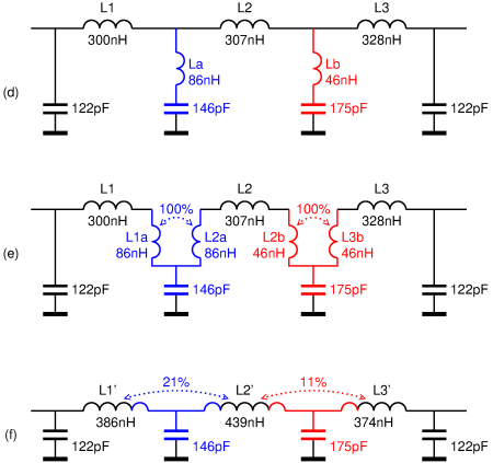 Next, let's consider how notches can be created due to coupling between coils; see the next figure.
Design (d) again resembles design (a) without notches; there still is no coupling between coils,
but extra coils La and Lb have been inserted in series with two of the capacitors.
These coils La and Lb, together with their series capacitors, form resonant circuits which short-circuit the signal to ground at their resonant frequencies,
and thus give notches.
The filter curve is the same as in the previous design (c) which used parallel, rather than series, LC circuits.
Schematic (e) is the same as (d), but drawn a bit differently: the coil La has been replaced by two fully-coupled coils L1a and L2a
(together they effectively are a 1:1 transformer).
Similarly, Lb has been replaced by L2b and L3b.
But electrically, nothing has changed.
Now we observe that L1a is in series with L1: together they are a coil of 300 + 86 = 386 nH;
this becomes L1' in figure (f).
Similarly, L2a and L2b are in series with L2, forming L2' of 439 nH, and L3b and L3 together are L3' of 374 nH.
In making this replacement, we must not forget the coupling: while originally L1a and L2a were coupled by 100%,
there is now just 21% coupling between L1' and L2' (calculated as 86/√(386×439)).
And similarly, the coupling between L2' and L3' is 11%.
Going from (d) to (f) we didn't change anything from an electrical point of view,
so the schematic (f), featuring coupled inductors, must have the same characteristics, including the notches,
as schematic (d) featuring series LC circuits.
Toward something reproducible
We've seen that with coupled coils we can make notches, and thus a steeper filter. But the mechanical construction from the first photograph is not so practical: the filter must be manually tuned using a network analyzer (tuning here is a eufemism for 'bending coils back and forth') and is fragile. Thus, the idea arose to make a reproducible version by designing a coilformer that can be 3D-printed, and which allows one to wind coils that have exactly the right inductance and coupling, without tuning. The design process for this should consist of three steps: first making an electronic design (capacitances, inductances, coupling factors), then a magnetic design (sizes and positions of the coils), and finally a printable mechanical design.
Step 1: electronic design
For designing 'normal' filters, with non-coupled coils, and also for filters with parallel LC circuits (figures (a) and (c)), there are ready-made tables and computer programs to calculate the correct values of the capacitances and inductances. But I haven't found such a table or program for filters with coupled coils or series LC circuits.That's why I initially started with a standard low-pass filter without notches. In a simulation program (like puff or ngspice) I added coupling between the coils, and played around with the coupling factors, capacitances and inductances, trying to make the frequency characteristic nice. But there are limits to what one can achieve with such trial&error: there are simply too many 'knobs' to turn (four capacitors, three inductors, and two coupling factors) to make the passband nicely flat. The solution for this is the so-called Darlington synthesis, a systematic method for calculating filters. That is also how I calculated the component values in filters (a)-(f) above. I'll write a separate article about this later.
Step 2: (electro)magnetic design
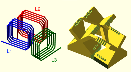 In this step, we determine how many turns of which size each coil will get for the inductance
calculated in the previous step,
and how far away from each other and under which angle the coils must be positioned
to get the right coupling factor.
That is again a matter of trying, with a computer program (LCnetgen) which, given the sizes,
number of turns and position of the coils, calculates the inductances and coupling factors.
Fortunately, the inductance of each coil is essentially independent of the presence of other
coils nearby.
Therefore, it is possible to first design the coils separately for correct inductance,
and afterwards position them for the right amount of coupling.
Still, it's a puzzle; particularly when a relatively large amount of coupling is needed,
the coils may get so close that they bump into each other.
Step 3: 3D-printable design
Now that we know how the wires must be shaped, the only thing remaining is designing a coil former to keep the wires in their correct place. The fact that it must be 3D-printable, does impose some restrictions: the details can't be too fine and the shape must be such that during printing it has sufficient 'support': one can't print a piece of plastic just randomly in the air. I make such designs using OpenSCAD, in which one describes the design in a programming language. That's handy because the previous step already gave me the coordinates of the wires.Step 4: trying, refining, and starting over
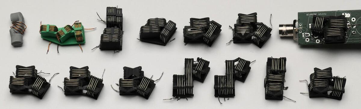 The three steps above sound as if they just need to be done once, but practice was different.
In the end, I made some 15 versions.
(I might not have started if I had known this in advance...)
The very first version (gray, top left) had cylindrical coils. Therefore it could only be printed in two halves, and was very unpractical to actually wind. Starting with the second version (green), I gave the coils an almost square shape, making printing much easier. The green filter worked okay, but the notches were rather far away from the passband making the filter less steep than desired. After implementing the Darlington synthesis, I could design filters with notches closer to the passband. But when I built them, they did not work as desired: the passband was nice and smooth, but the stopband was wrong: there were either no notches at all, or they were too far apart.
What followed was a long search for the cause. I gradually refined the electromagnetic model to take more details into account, such as the inductance of the capacitor wires; the fact that the wires in the coils are a bit 'slanted' because every next turn is about a millimeter further along the axis; the influence of the copper surface that was used as a support to give the capacitors a good ground connection, but which also acts as a mirror; and the capacitive coupling between the coils, separately from every piece (partial turn) of coil to every other piece of coil. And then every time again updating the design, printing a new version (with thanks to our local radio club member Albert for that), with great hope building and measuring it, and noting that it again is not right. Furthermore, it turned out that details that are hard to include in the model, such as the precise location of the capacitors, had a measurable influence.
The real problem
Only after a lot of trying and refining of the model, it became clear to me where the problem really was: undesired coupling between L1 and L3. That coupling should be zero or almost zero. Because L1 is at the input and L3 at the output of the filter, in the stopband the currents and voltages at L3 are very much smaller than at L1: up to 1000 times in case of 60 dB of attenuation. Therefore, a very small amount of coupling can quickly be too much. Normally one would solve that by shielding L1 and L3, placing them further apart, and/or using toroidal cores. But those are not an option here, because both still need to be coupled quite strongly to L2 to obtain the right notches.Thus, unavoidably, L1 and L3 are not very far apart, and between individual turns of each of those coils there is a lot of coupling, not only inductively but also capacitively. Depending on their mutual position, the inductive coupling between turns can be positive or negative. When some turns are coupled positively and others negatively, the net results may be zero; this happens for example if the coils are at right angles to each other. Such a balance of positive and negative contributions is what we search for in step 2 of the design process. But that balance is very sensitive to small errors: small deviations in the exact positioning of the wires, or inaccuracies of the modelling. For example, LCnetgen can only calculate the influence of an infinite copper plane, not of a smaller plane or a plane with interruptions (traces on the circuit board).
When I couldn't improve the modelling further, a difference between theory and practice remained. That difference had to be due to the slightly wrong coupling between L1 and L3. When I moved L3 by just 0.4 mm in the model, the calculated characteristics matched the measurements. Such a small move of L3 almost exclusively changes the coupling between L1 and L3; the inductances and other couplings hardly change. Therefore, in the final printed version I moved L3 0.4 mm in the opposite direction, hoping to cancel the error. Indeed, that helped, albeit not perfectly.
Final result
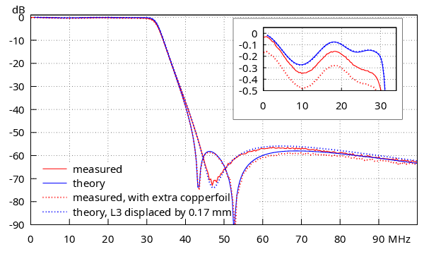 The filter's final characteristics are in this graph.
The solid red line is measured on the actual filter,
and solid blue is the theoretical curve for comparison.
Clearly, the match isn't perfect yet.
Undesired coupling between L1 and L3 shows itself mostly in moving the notches
farther apart or closer together.
The latter happened here: the notches merged, resulting in a broader and less deep notch.
The dotted blue line is the result of moving L3 in the simulation by 0.17 mm: this curve fits the measurements almost perfectly.
Conversely, holding a piece of copper foil at just the right spot near the coils during the measurement,
gives the red dotted line, which almost perfectly fits the original theory.
Both of these indicate that theory and practice are already very close.
We're not going to get it much better than this: it depends too much on manufacturing tolerances and the environment.
Conclusion
The idea was that this technique would give easily reproducible low-pass filters for HF transmitters.
That has largely been achieved, except that the stopband attenuation of 60 dB is
just a bit too much for practical reproducibility.
And looking back, that was perhaps to be expected:
with coupled coils, and no shielding, it's hard to prevent the signal from leaking around the filter a bit...
Text and images on this page are copyright 2026, P.T. de Boer, web@pa3fwm.nl .
Republication is only allowed with my explicit permission.